Radio CommunicationsAn introduction to electromagnetic radiation, antennas, and modulation. |
Version | v1.0.0 | |
|---|---|---|---|
| Updated | |||
| Author | jtriley2p | License | AGPL-3 |
Radio communications is the backbone of all modern wireless communications technology, from GSM cell networks and Wifi to amateur radio and satellite telemetry.
Though most modern radio communications happen in standardized frequencies with standardized hardware and protocols, amateur radio operators are licensed to experiment with different frequencies, modulation techniques, and hardware customization beyond standardized products. Originally, amateur radio in the United States in particular, was a civil defense organization. In times of crisis, public events, or in the modern era, internet blackouts, amateur radio operators can form networks of transmitters, receivers, and repeaters to create an adhoc communications network.
In the following article, we’ll explore some of the introductory concepts in the electromagnetic spectrum, antenna design, and modulation techniques.
The electromagnetic spectrum is the basis for all modern wireless communication including bluetooth, wifi, cell networks, radio, and television, as well as the visible light spectrum, and even harmful radiation such as ultraviolet and x-ray radiation. The differentiator between each of these is the wave’s frequency, measured in oscillations (or cycles) per second, denominated in Hertz (Hz). One Hz represents one full sine wave per second, while one megahertz (MHz) represents one million Hz per second.
              1MHz     1GHz    1THz    1PHz    1EHz    1ZHz
            ┌──┴───────┴───────┴───────┴───────┴───────┴──┐
            └─┬──┬──────┬┬──────────┬──┬─┬──┬─────┬───┬───┘
     ┌────────┘  │      ││          │  │ │  │     │   │
     │   ┌───────┘┌─────┘│    ┌─────┘  │ │  │     │   └──────┐
     │   │   ┌────┘┌─────┘    │        │ │  └┐    └───┐      │
     AM  FM  Wifi  Microwave  Remotes  │ │   Sunburn  X-Ray  Nuclear
                                    ┌──┘ └──┐
                                 ┌──┘       └──┐
                              ┌──┘    Visible  └──┐
                           ┌──┘        Light      └──┐
                           ├───┬───┬────┬────┬───┬───┤
                           R   O   Y    G    B   I   V
| Abbreviation | Prefix | Value |
|---|---|---|
| kHz | Kilo | 103 |
| MHz | Mega | 106 |
| GHz | Giga | 109 |
| THz | Tera | 1012 |
| PHz | Peta | 1015 |
| EHz | Exa | 1018 |
| ZHz | Zetta | 1021 |
The wavelength (λ) of an electromagnetic wave is a function of its frequency (f), in Hz, and the speed of light (v), in meters per second.
     v
λ = ───
     f
Light travels at 300,000,000 m/s, as such, the function for wavelength is as follows.
# 300,000,000 meters per second
speed_of_light_ms = 300_000_000

# 2.4 gigahertz
frequency_Hz = 2_400_000

# 0.125 meters aka 12.5 centimeters
wavelength_m = speed_of_light_ms / frequency_Hz
Amateur radio operators and technicians also tend to further break down the classes of electromagnetic energy into three sub ranges, the High Frequency (HF), Very High Frequency (VHF), and Ultra High Frequency (UHF) bands.
| Frequencies | Wavelengths | Subrange |
|---|---|---|
| 3-30 MHz | 100-10m | HF |
| 30-300 MHz | 10m-1m | VHF |
| 300-3000 MHz | 1m-0.1m | UHF |
Different frequencies of electromagnetic radiation are affected by different phenomena in our environment in different ways, though we can broadly group these into the subranges mentioned above.
High Frequency (HF) waves can bounce off of the the “E” layer of the ionosphere, an upper section of Earth’s atmosphere which is ionized primarily by solar radiation. This is generally referred to as “sporadic E” propagation, as the phenomena which affect the ionization of the ionosphere can be sporadic. Sunspots, for example, increase and decrease on an 11 year solar cycle and when there are more sunspots, the ionization is stronger, and so is HF propagation. The aurora can interfere with HF propagation, a phenomenon known as auroral scatter. Precipitation in the troposphere often does not have significant effects on HF propagation.
Very High Frequency (VHF) and Ultra High Frequency (UHF) are generally only capable of line-of-sight communications, as they are blocked by the curvature of the Earth and are not propagated by the ionosphere. The maximum line-of-sight distance, also known as the radio horizon, does extend further than the visual horizon, as the atmosphere slightly refracts radio waves. VHF and UHF waves can be bounced off of surfaces such as buildings or obstructions. They can also be diffracted around sharp obstacles in a bizarre phenomenon called knife-edge diffraction. Heavy vegetation and precipitation can absorb UHF waves. However, auroral scatter can better propagate VHF/UHF, as can meteor showers by bouncing waves off of the ionized tails of the meteors, though the latter is quite sporadic. Troposcatter is the random scatter of the troposphere which can propagate VHF further. Tropospheric ducting can occur during a “temperature inversion”, where cold air is trapped beneath warm air, and VHF signals can propagate much further.
Multipath distortion is a phenomenon where radio waves, through scatter or through bouncing off of varying surfaces, arrive at a receiver from different paths. This becomes a problem if the signals are received in different phases or if the signals destructively interfere with one another. Moving the transmitter or receive even a few meters can drastically affect received signal strength.
The way we transmit radio signals (typically frequencies up to 300GHz), is by creating a resonant circuit, that is a circuit with an oscillating electromagnetic field, and an antenna to radiate its electromagnetic energy.
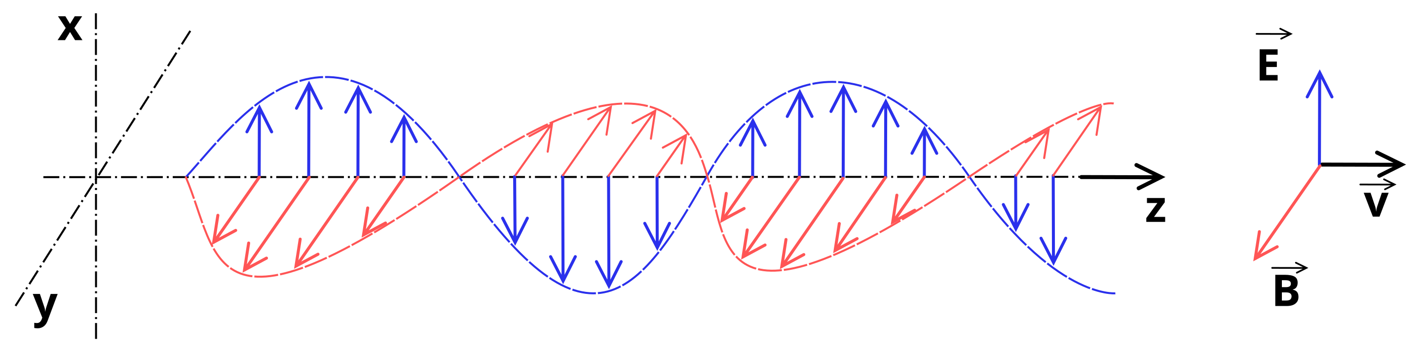
When transmitted, electromagnetic waves consist of an electric field and a magnetic field, which move perpendicular to one another.
The polarization of an antenna indicates the angle at which the electric field moves. Vertical polarization means the electric field is radiated vertically and the magnetic field is radiated horizontally. Horizontal polarization is the opposite of this. VHF and UHF antennas transmit and receive signals at a much higher strength when polarizations match.
Antennas should also be a length proportional to the wavelength.
Simple linear antennas include monopoles and dipoles. These interact with the electric field and transmit strongest along their broadside. The length of the simple linear antenna should be either the wavelength or a fraction of it such as half or a quarter for better reception quality.
             \
   .      \   |
   │    \  |  |
   │    /  |  |
   │      /   |
┏━━┻━━━┓     /
┃ TX   ┃
┃      ┃
┗━━━━━━┛

           │         \
           │      \   |
┏━━━━━━┓   │   \   |  |
┃ TX   ┣───┘ \  |  |  |
┃      ┣───┐ /  |  |  |
┗━━━━━━┛   │   /   |  |
           │      /   |
           │         /
Rubber ducky antennas are commonly seen on walkie talkies and other more compact radio transceivers. These often have a thick plastic cover, but underneath the antenna is short, often coiled, and loaded with an inductor to better receive signals.
 ┏━━┓       \
 ┃╭╯┃    \   |
 ┃╰╮┃  \  |  |
 ┃╭╯┃  /  |  |
 ┃╰╮┃    /   |
┏┻━┻┻━━┓    /
┃ TX   ┃
┃      ┃
┃      ┃
┗━━━━━━┛
Phased array antennas are composed of multiple antennas laid out in a two or three dimension array with relative phase offsets between them such that their wave constructively and destructively interfere with one another. Phase will be discussed in the phase modulation section below. In some phased array antennas, the relative phases can be adjusted by an electronic controller to create a beam of radiation via constructive interference and even change its angles. Modern radar uses phased array antennas to sweep the search space with a more powerful, focused beam of electromagnetic energy.
          │                      \
          │   │               \   |
┏━━━━━━┓  │   │   │        \   |  |
┃ TX   ┣──┴───┴───┴──┘   \  |  |  |
┃      ┣──┬───┬───┬──┐   /  |  |  |
┗━━━━━━┛  │   │   │        /   |  |
          │   │               /   |
          │                      /


┏━━━━━━┓          \
┃      ┃ │   \     |           \
┃ TX   ┣═╣    |    |            \
┃      ┃ │   /     |       \     |
┃      ┃          /   \     |    |
┃      ┃ │    \        |    |    |
┃      ┣═╣     |       |    |    |
┃      ┃ │    /        |    |    |
┃      ┃          \   /     |    |
┃      ┃ │   \     |       /     |
┃      ┣═╣    |    |            /
┃      ┃ │   /     |           /
┗━━━━━━┛          /
There are other antennas such as loop antennas, helical antennas, and many, many more, though these are beyond the scope of the article.
Modulation is the process of altering the parameters of the electromagnetic waves such that they carry information. A sine wave alone carries no information aside from its parameters, that is amplitude, phase, and frequency. We can manipulate each of these parameters, as well as multiple parameters, to transmit information on the electromagnetic radiation. The sine wave transmitted is known as the carrier wave, while the wave which conveys information is the signal wave, and the transmitted signal is a combination of the carrier wave and the signal wave.
There are two broad classes of modulation techniques, analog and digital. The analog signal wave corresponds to an analog signal such as sound waves, while a digital signal wave may correspond to a given bit or a series of bits.
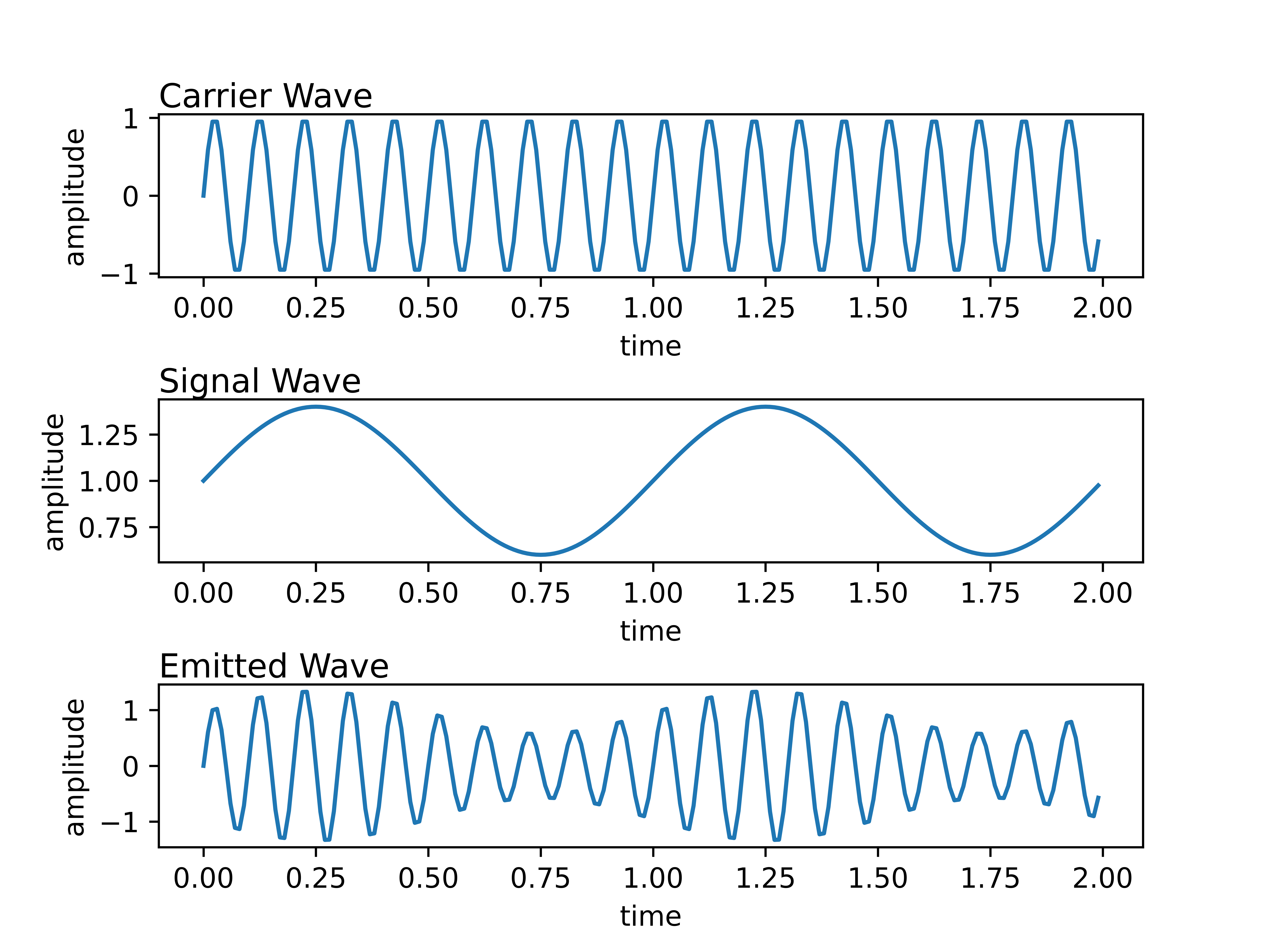
Amplitude modulation is the process of applying a signal wave to the amplitude of the carrier wave, that is the amplitude or power of the transmitted wave increases and decreases with the signal’s amplitude. Amplitude modulation is common used in AM radio broadcasts, some shortwave and HAM radio transceivers, aircraft radio, and in tandem with other modulation methods, though this will be described in depth later in the article.
The following is an example of analog amplitude modulation to transmit a wave of lower frequency, such as that of a sound wave.
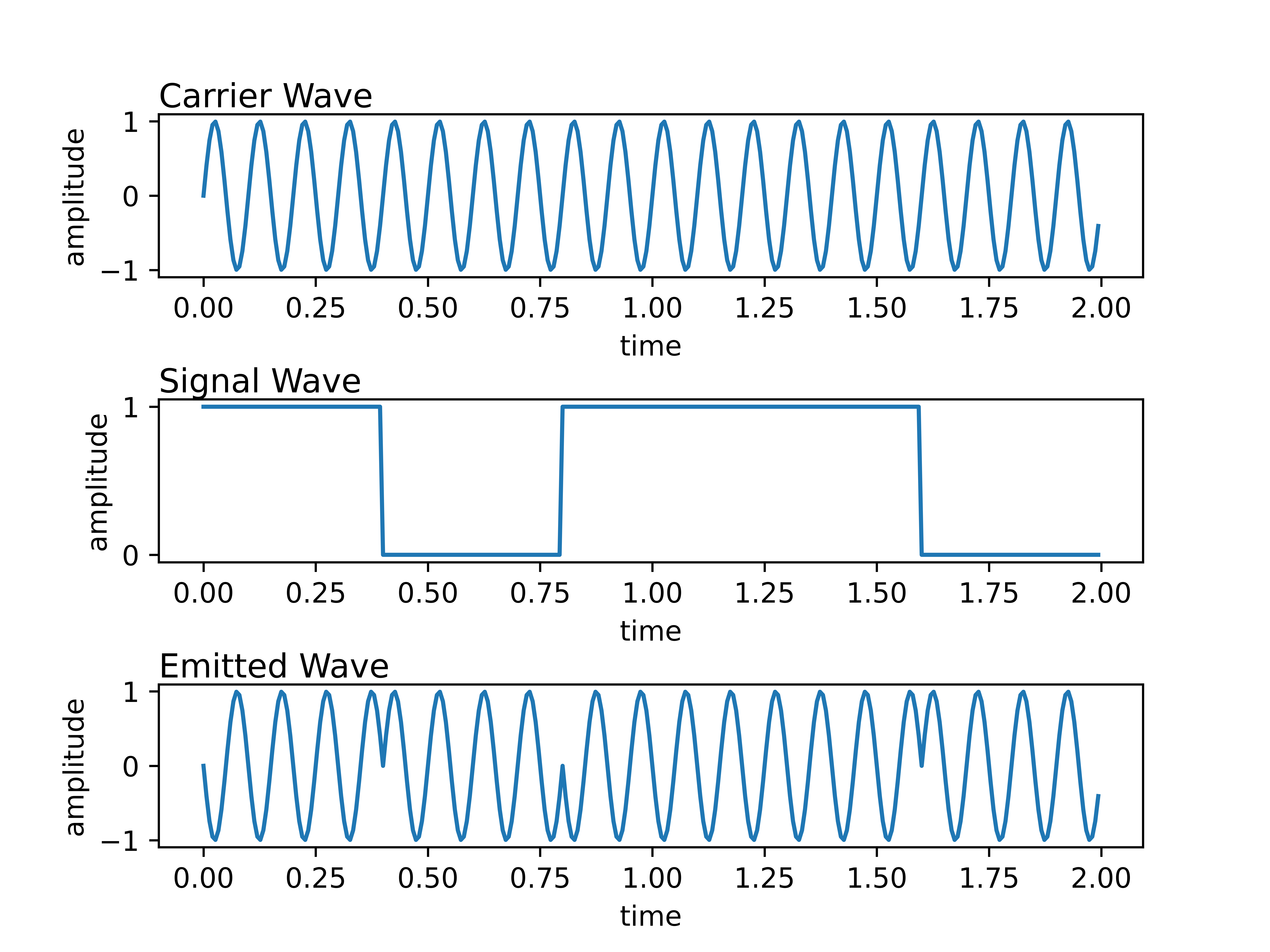
Additionally, we can use amplitude modulation for digital transmissions, where an amplitude of zero is the zero bit and the standard amplitude is the one bit. We refer to this as amplitude-shift keying, as the amplitude maps to a “key” or a bit. ASK transmissions are commonly used in transmitting over fiber optic cables.
Note how the signal wave is not a smooth wave, but rather a square wave such that it is either in the zero or one position and note how that affects the emitted wave.
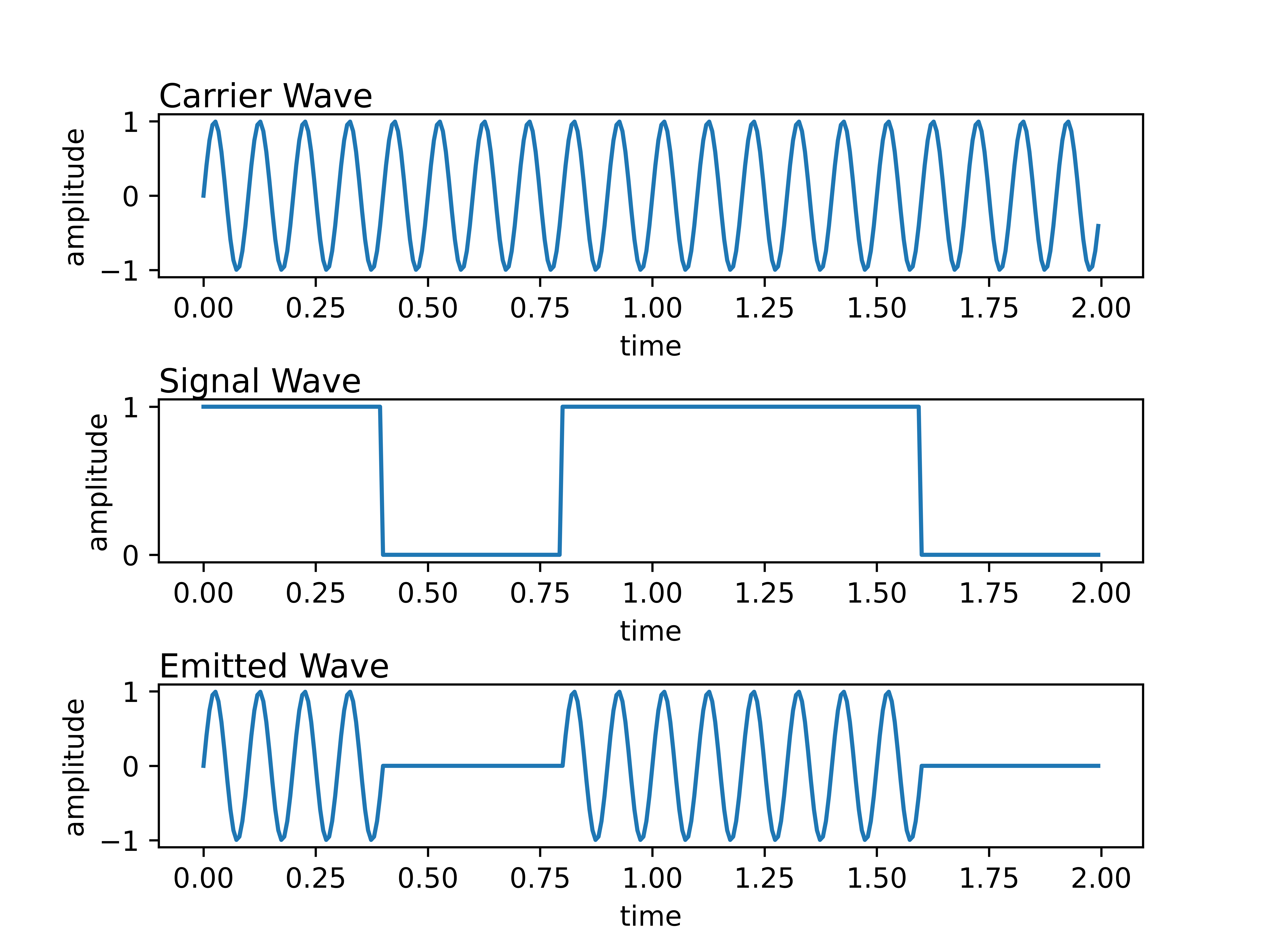
In the above example, we transmit 1 0 1 1 0 and we use a
standard number of oscillations for each bit in a tradeoff between
bits-per-second transmitted and the probability that the receiver
received the correct sequence of bits. This can also be improved with
error correction strategies.
Frequency modulation manipulates the carrier wave by increasing and decreasing the carrier wave’s frequency via the signal wave. It is worth mentioning that this takes up more bandwidth than amplitude modulation, as a frequency modulated transmission must occupy multiple frequencies throughout the transmission. This is often used for FM radio broadcasting and shortwave radio communications. Note that frequency modulation has a higher signal-to-noise ratio than amplitude modulation with similar transmission power.
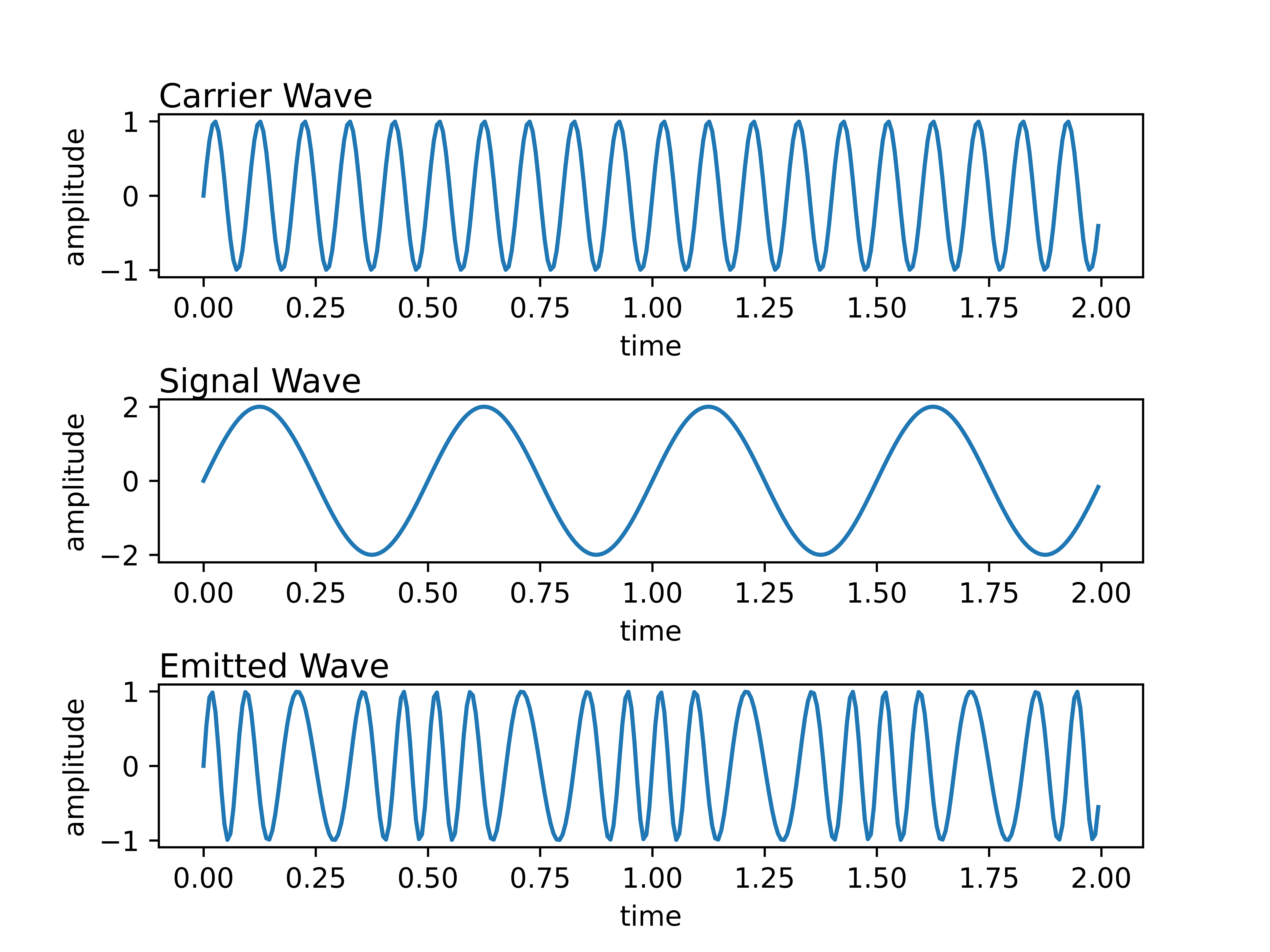
Frequency-shift keying is similar to amplitude-shift keying, though with frequency differences representing bits transmitted. FSK is used in low frequency transmissions such as garage door openers, telemetry systems, and weather balloons.

Once again, we transmit 1 0 1 1 0 and we use a standard
number of oscillations in our transmissions.
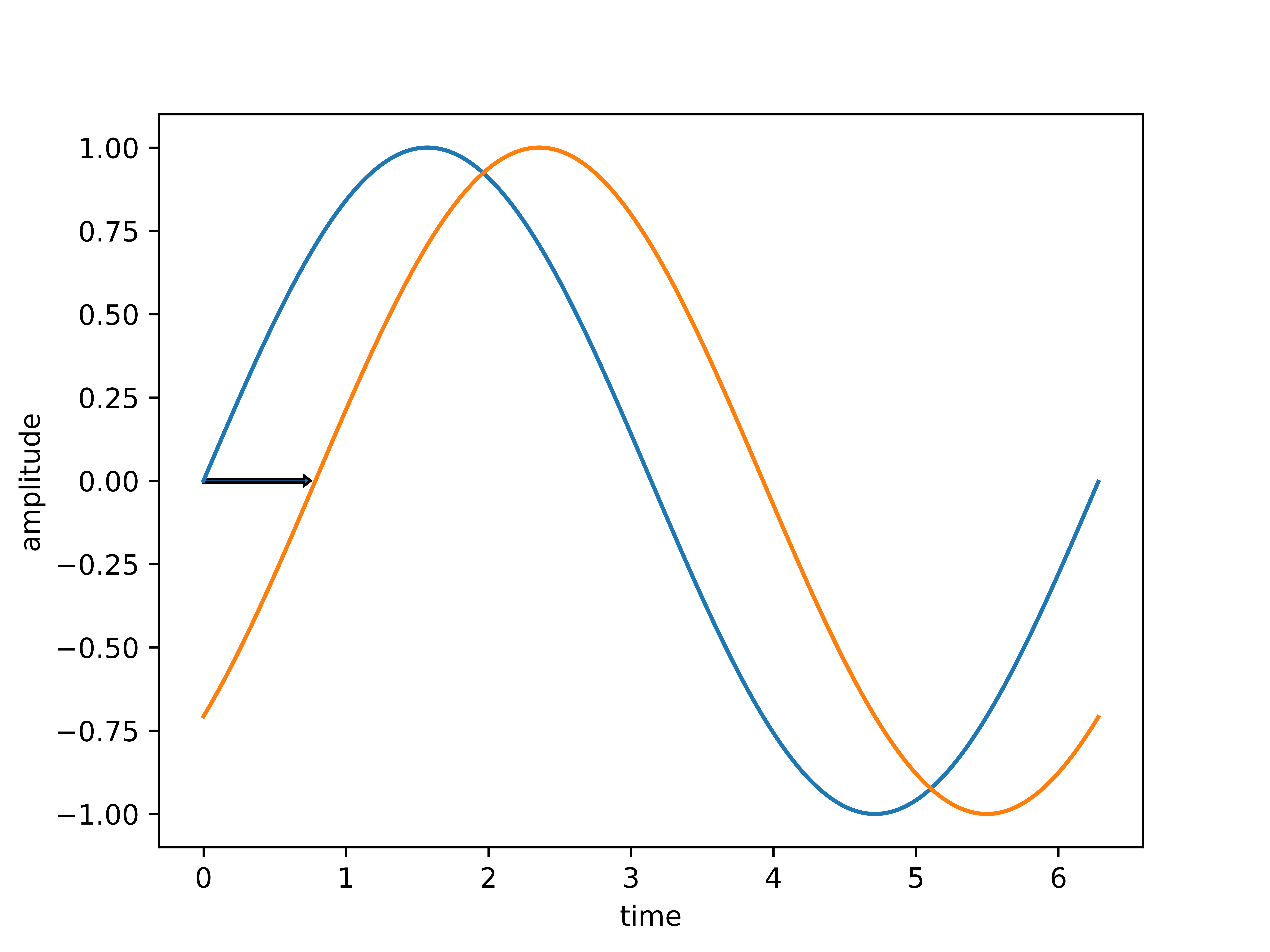
As a prerequisite, phase, in particular, refers to the offset of a given sine wave from a reference sine wave. We represent phase in degrees, where the phase offset between identical waves is 0° and the phase offset between two opposite waves is 180°.
The following image is a blue reference wave and a red wave at a phase offset of 45°.
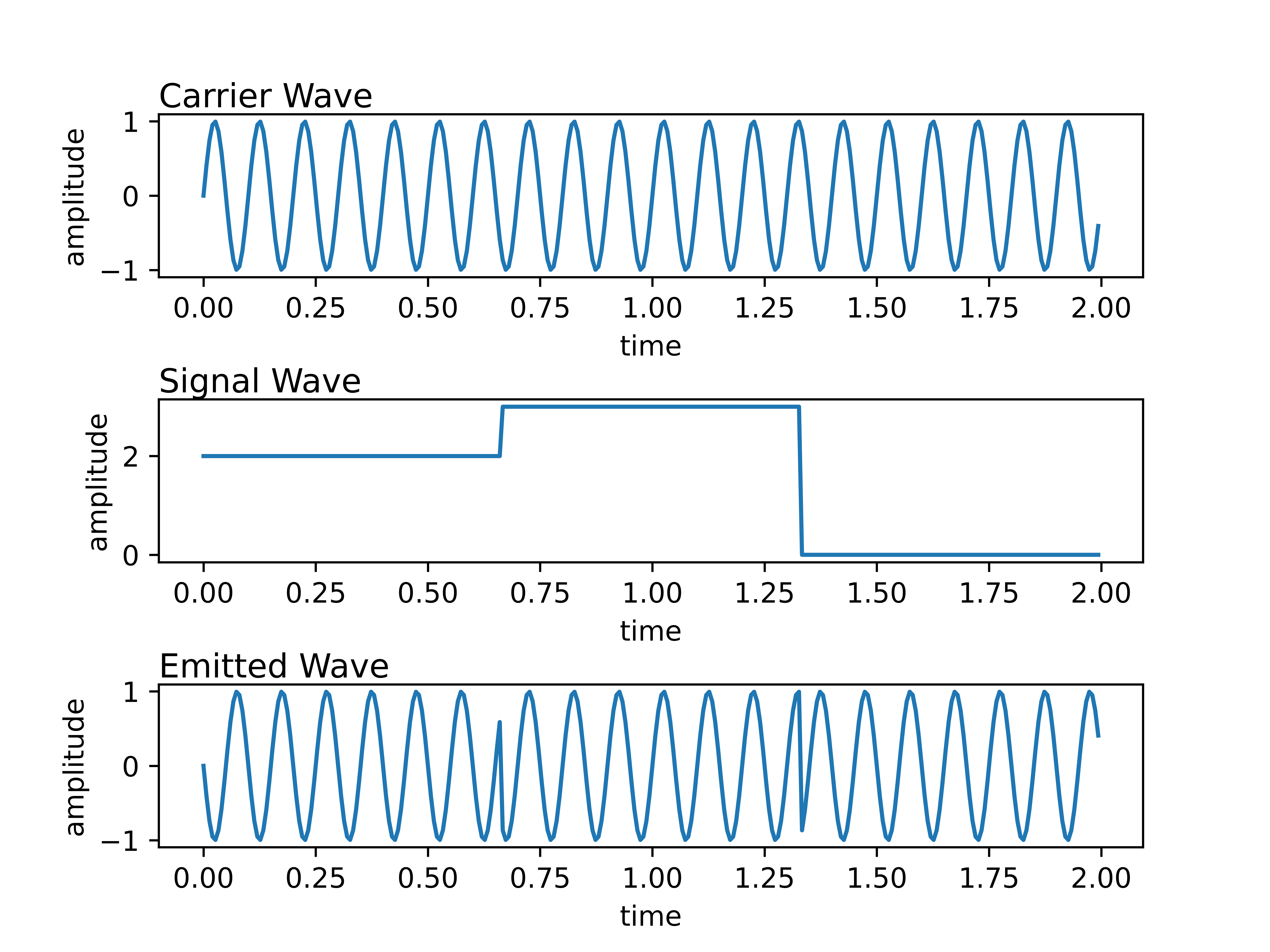
Phase modulation manipulates the relative phase of the carrier wave with the signal wave. Analog phase modulation is possible, though it is not commonly used in radio transmissions. Phase-shift keying, however, is a critical component in modern radio communications systems such as Wifi, GSM, Bluetooth, and more.
Note how when the bit changes from zero to one or one to zero, the wave appears to invert and continue its oscillation from where it inverted. The “signal” is explicitly in the change in phase.
Once again, we transmit 1 0 1 1 0 and we use a standard
number of oscillations in our transmissions.
Note that there are not only two phases in which a wave can exist, our example above only uses binary phase-shift keying (BPSK), but we can also use multiple phases such as quadrature phase-shift keying (QPSK). QPSK allows the signal wave to have four states instead of two (zero and one). We can map each of the four states to a pair of bits:
By using quadrature phase-shift keying, we can transmit double the data for each phase shift, either increasing the bits-per-second or increasing the redundancy in bits transmitted.
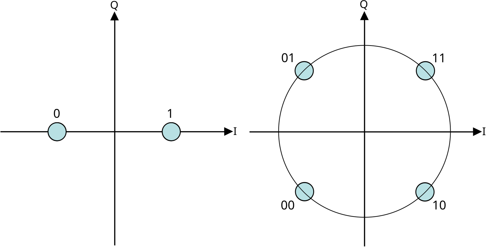
We can represent these in an alternative diagram called the constellation diagram. The constellation diagram maps the phase in the sine wave to an angle on the unit circle.
In the binary phase-shift keying constellation diagram, the bits zero and one are at phase offsets zero degrees and 180 degrees. In the quadrature phase-shift keying constellation diagram, however, the pairs of bits are at the offsets of 45, 135, 225 and 315 degrees. Each angle represents a phase in the transmitted wave which represents some “keyed” information.
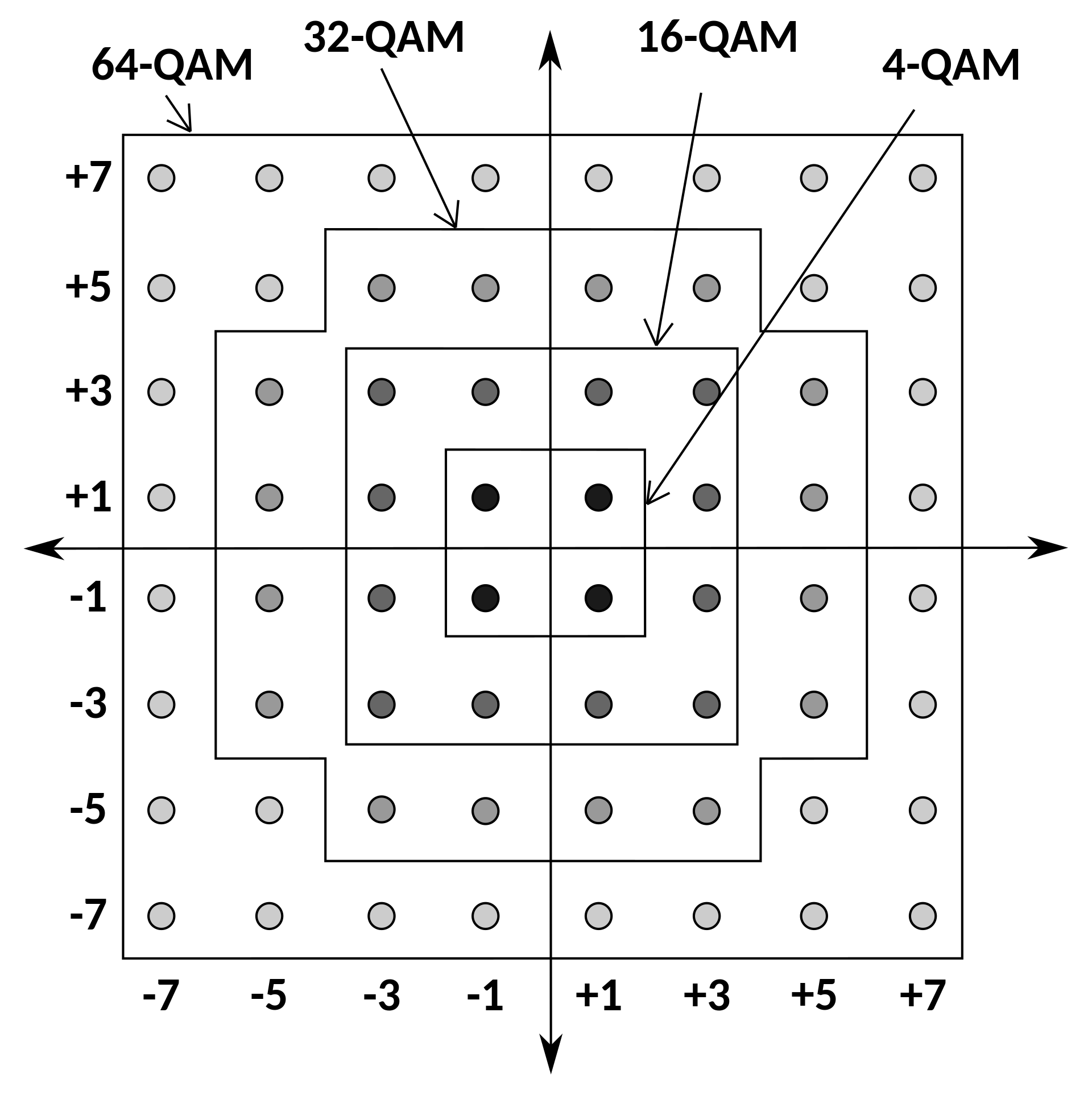
The cutting edge in modulation techniques includes the quadrature amplitude modulation (QAM) strategy. We can combine the techniques of amplitude-shift keying and phase-shift keying to create potentially many combinations of bits to transmit at a time. 4-QAM is akin in implementation to quadrature phase-shift keying, 16-QAM incorporates phase and amplitude shifts, as does 32-QAM, 64-QAM, 128-QAM, and even 256-QAM! We can use a constellation diagram akin to the one above to visually represent the collections of bits and how they may be mapped in some of these schemes.
There are many more topics that could be expanded upon here such as multiplexing signals for increased bit rates, transforming signals into the frequency domain with fast fourier transforms, error correction, new improvements in the open source and public standardization space for mesh networking, and much more. Though this article is getting long, so this will be all for now.
I hope this was insightful to beginners and intermediates alike, if you’d like to see more articles like this one in the future, please reach out and let me know!
Until next time.